.webp)
This “stops and extends at the touch of a button” telescoping luggage handle is actually a traditional “spring-steel ball-cage” mechanical locking mechanism. Three steps comprise the entire telescoping process: unlocking, free sliding, and automatic locking.
Below, we will disassemble the inner and outer tubes, button, spring, steel ball, and stamped lock. Describe why the retractable luggage handle won’t slide down by itself and why it clicks and stops in sections.
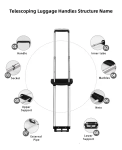
Telescoping Luggage Handle Core Parts List
Outer Tube: It attaches to the section closest to the luggage body. And we rivet its bottom to the plastic base.
Inner Tube: Consists of 1 para 3 seções, retracts in stages; we rivet the “handle assembly” to the top.
Lock Block, riveted to the bottom end of the inner tube, containing:
- Horizontal locking pin or horizontal “U”-shaped spring
- 1-2 high-hardness steel balls (Ø3 mm)
- 1 compression spring
Hole arrangement on the outer tube: Punch a pair of symmetrical Ø4 mm circular holes every 25 mm (typical) along the axis to form the “gear” positions.
Handle Assembly = Plastic Shell + Push Button + Small Steel Wire/Connecting Rod + Return Spring.
Locked (Default)
The compression spring pushes the locking pin/ball outward, and the pins simultaneously insert themselves into the left and right holes of the outer tube. → The inner and outer tubes connect to form one piece, preventing the lever from sliding up or down; this is the source of the “stuck” problem.
Unlocking (Push Button)
Hit the handle button. → The tiny connecting rod inside the plastic shell descends 4–6 mm. → The connecting rod presses up against the ball or locking pin.
As a result, the pin retracts into the inner tube wall, compressing the spring. The rod can freely extend and retract as the system loses the mechanical connection between the inner and outer tubes, leaving only a small amount of resistance from the nylon sleeve.
Sliding and Automatic Relocking
Still pressing the button, pull the rod to the desired length. Once released:
The spring rebounds. → The spring pushes the locking pin/ball outward again. → It clicks into the first set of holes. → It reengages and automatically locks.
Because the holes are equidistant, multi-stage locking is possible.
Anti-rotation and Wear-Resistant Features
Anti-rotation: To keep the buttonholes aligned during extension and retraction, we cut a matching groove into the inner tube and press a 0.5 mm rib into the inner wall of the outer tube.
Wear resistance: We position 1-2 POM sleeves (or nylon bushings) on the inner tube’s lower end to dampen noise and vibration. And compensate for the ±0.05 mm gap that the extrusion process creates.
Common Causes of Failure
The lock pin/ball becomes rounded due to wear; it cannot fully retract, resulting in “auto-retraction.”
Luggage dents the edge of the outer tube hole. → The pin cannot be pushed out.
The plastic column of the connecting rod is broken → the button “presses in vain” with no downward pressure;
The sleeve is worn through → the vibration increases, making the handle feel “loose.”
In a nutshell
The telescoping luggage handle lever is a classic mechanical solution: a spring pushes the ball/pin into the hole to lock it, and the button uses a connecting rod to pull the pin back into the hole to unlock it. It has a simple structure, low cost, and is maintenance-free. Portanto, it has remained virtually unchanged for two decades, with the only change being the material from iron to stainless steel or ceramic beads, which offer longer life and a lighter feel.
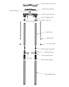
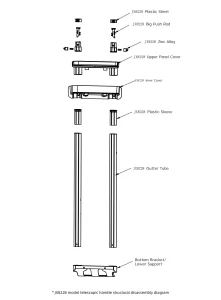
JX8228 Model Telescopic Handle Structural Disassembly Diagram. (Part 1) JX8228 Model Telescopic Handle Disassembly (Part 2)